Free Gear Ratio Calculator & Simulator - Speed, Torque & Gear Train Designer
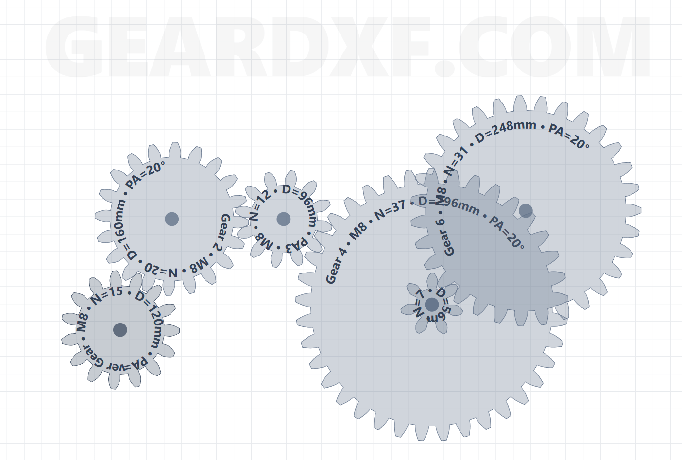
GearDXF is the most powerful free online gear ratio calculator and real-time gear train simulator. Calculate velocity ratios, mechanical advantage, output torque multiplication, and shaft RPM across single-stage pairs, compound gear trains, planetary drives, and idler assemblies. Visually simulate gear rotation in your browser and export production-ready DXF, SVG, and printable 1:1 PDF files for laser cutting, CNC machining, and 3D printing.
Single-Stage Gear Ratio & Velocity Formulas
For two meshed gears, the gear ratio (R) is determined by the ratio of their tooth counts: R = N_driven / N_driver = d_driven / d_driver. The output rotational velocity is inversely proportional to the gear ratio: ω_out = ω_in / R, or RPM_out = RPM_in / R. When the driven gear is larger than the driver gear (R > 1), the system acts as a speed reducer and torque multiplier.
Torque Multiplication & Mechanical Advantage
Mechanical power is conserved between gear stages (Power = Torque × Angular Velocity). Ignoring minor frictional losses, torque is multiplied by the gear ratio: T_out = T_in × R × η (where η is mechanical transmission efficiency, typically 95% to 98% for precision spur gears). High reduction ratios enable small electric stepper or DC motors to lift heavy mechanical loads.
Compound Multi-Stage Gear Trains
To achieve high reductions (such as 50:1 or 100:1) without unwieldy, massive gear diameters, compound gear trains mount two gears of differing tooth counts onto a shared intermediate shaft. The overall gear ratio is the product of the individual stage reductions: R_total = R_1 × R_2 × R_3... GearDXF lets you link compound axles and calculates compound reductions automatically.
Idler Gear Mechanics & Direction of Rotation
Inserting an idler gear between two gears reverses the direction of the output shaft without altering the gear ratio: R = N_output / N_input. GearDXF's visual builder highlights rotational direction arrows on every gear, making it effortless to plan clockwise and counterclockwise motor outputs for clock mechanisms and robotic drivetrains.
Shaft Center Distance Calculations
Precision gear train housings require exact axle hole drilling coordinates. GearDXF computes the center-to-center distance between mating spur shafts using the standard formula: a = Module × (z_1 + z_2) / 2. This guarantees tangential pitch circle alignment and zero binding when drilling mounting plates.
Interactive 2D Gearbox Simulation & CAD Export
Test your calculations immediately. Enter your motor RPM, start the live simulation, and watch your multi-gear train rotate with true relative angular velocities. When satisfied with speed and clearances, export the complete vector assembly in DXF, SVG, or printable 1:1 scale PDF for digital fabrication.
Frequently Asked Questions (Gear Ratios)
How do I calculate a gear ratio? Divide the number of teeth on the driven gear by the number of teeth on the driving gear: Ratio = Driven Teeth / Driver Teeth.
What is the effect of a gear ratio greater than 1? It reduces output speed while multiplying output torque (speed reduction / torque increase).
Does an idler gear change the gear ratio? No, an idler only changes the direction of rotation and spans physical distance.
How do compound gear trains work? Multiple gear pairs on shared intermediate shafts multiply their individual ratios together (Total Ratio = R1 × R2).
- Robotics Gearboxes: Optimize motor torque and speed for arm joints and rover wheels.
- Mechanical Clocks: Calculate 60:1 and 12:1 gear trains for second, minute, and hour hands.
- Automotive & Drivetrains: Determine final drive ratios and transmission step-downs.
- Winch & Hoist Systems: Calculate mechanical advantage for heavy lifting equipment.
100% free client-side tool. Your designs remain private and secure on your device. No registration or credit card required.